4-Bar Steering Mechanism
- Bryden

- Apr 7, 2020
- 4 min read
Updated: Apr 10, 2020
To determine the steering mechanism of the trike, we brainstormed and looked to various ideas and real solutions to provide an understanding of a potential method to create hands-free steering. The search led to an idea of using a 4-bar mechanism to drive the steering column via an onboard motor. From this idea, we used the software SAM to create a 4-bar mechanism which helped us determine the angles we would be able to reach with our mechanism, as well as the general dimensions of the 4-bar mechanism.

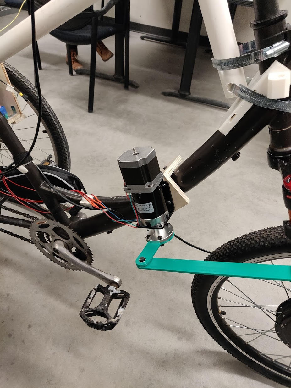
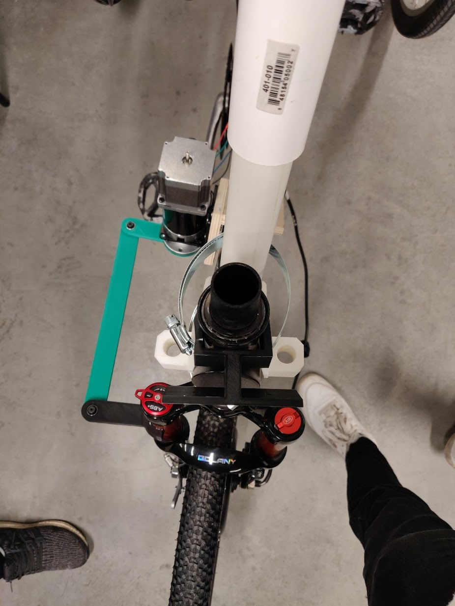
From this point, we decided to put our 4-bar mechanism to the test by creating a physical prototype through use of 3D printers. Through 3D printing, we were able to create the short and long links of the 4-bar mechanism, as well as the required nut and bearing. However, due to tight tolerances and issues with printer calibration, it was difficult to produce a fully serviceable product. As a result, we created the prototype using metal bearings and nuts that were purchased, along with the 3D printed links. (insert photo of steering mechanism prototype)

Along with creating the prototype, we needed to determine what would be required for the driving motor of the steering mechanism. For this, we performed a series of tests to determine the required motor torque necessary to steer the trike. The tests that were performed for the torque analysis was done by measuring the required force to turn the steering column by pulling with a fish-hook scale perpendicularly from the handlebars. Each test trial began with the front trike wheel facing the farthest right position and ended when the wheel was turned to the farthest left position. The maximum force required to turn the steering column for each trial would then be recorded. The test was performed 10 times. To ensure that the experiment simulated operational conditions, the following conditions were set: the trike was loaded with a weight of 230lbs, to safely approximate the user’s weight, and the test was performed on dry concrete. Additionally, two assumptions were made: the force pulling the steering mechanism was perfectly perpendicular to the handlebar, and the handlebar is parallel to the trike front wheel fork.
The choice of a 230lb load added onto the trike for testing was due to a few reasons. Firstly, we wanted to choose a weight that would reasonably simulate a user near the upper limit of the design constraints, which was 250lbs. However, due to safety reasons, we were unable to load the trike with a weight greater than 230lbs. As well, we were able to perform this test on ground that was similar to that of a bike trail, to emulate a realistic torque requirement during operation.
An assumption that we made for this experiment was that the handlebars were situated parallel to the trike fork. This assumption is important for the analysis because the trike fork is where the mechanism will be providing torque for the completed prototype. Therefore, with this assumption we were able to predict the torque requirement applied to the trike fork, with experimental results from the handlebars. Initially, we considered performing the test onto the trike front wheel fork, however it was difficult to connect the fish-hook scale to the fork. As a result, we chose to perform the test on the handlebars instead.
The average maximum force applied to the handlebars, from the cumulative 10 test trials, was found to be 3.848lbf. The moment arm from the connection point on the handlebars to the steering column was exactly 12 inches. Therefore, the required torque was calculated to be 5.217Nm. We chose a safety factor such that the design torque would be 6Nm.
Potential options for the chosen motor include DC motors, servo motors, or stepper motors. One large advantage for the stepper motor over the DC and servo motors is that the stepper motor reaches maximum torque at lower speeds and is generally used for applications where holding torque is a significant factor. For our application, the rotational speed of the motor will be relatively low. As well, holding torque will be a significant consideration as the motor will be required to pass a relatively large threshold torque, especially in situations where the trike is stationary, or when the tire is positioned to the far right or left end positions. For the stated reasons, the steering mechanism motor was chosen to be a stepper motor over the servo or DC motors.
After observing several options, the motor our group chose for the steering mechanism was a bipolar stepper motor that can provide 23.54Nm of torque at low speeds.
Another observation with respect to the torque analysis is the relatively low torque requirement for the steering mechanism. Due to the low torques found during our testing and analysis, our team decided that it would be advantageous to create the final prototype’s 4-bar linkage out of PLA (polylactic acid) from a 3D printer as the material is strong enough to withstand the bending, tensional, and compressive stresses that would be generated from the application. The choice of using PLA as the build material is advantageous due to the availability of an in-house 3D printer for our team, as well as the reduced difficulty in manufacturing the parts when compared to a metal 4-bar linkage design.


Comments