Battery Pack: Part 1 - Initial Research and Design
- Munifa

- Apr 7, 2020
- 3 min read
Updated: Apr 7, 2020
LEAD ACID VS. LITHIUM-ION
One of the first considerations when designing the battery pack was to research the various alternatives available; namely lead-acid and lithium-ion. Lead acid batteries are cheaper. Lithium-ion batteries offer a better depth of discharge, so you can drain comparatively more energy from it without damaging it. Lithium-ion technology also has a higher energy density, so it packs more energy in a smaller space and weighs less. Essentially, lithium-ion battery technology outperforms lead acid batteries in all categories except cost. For this reason, lithium battery packs are preferred in the e-bike industry, and that is what we opted to integrate into our design.
In order to reduce cost, our team reached out to local electronic recyclers to utilize lithium-ion cells from old laptop batteries to build our custom battery pack. One of these recycling companies, eCycle Solutions, generously agreed to provide old laptop batteries for our project.
SAFETY
We researched and identified the following potential risks of working with lithium-ion batteries and outlined a mitigation plan for each of the risks.
Risks
If a cell within the battery pack has significantly different capacity compared to other cells, then there is a risk that the cell will overheat. If the operating temperature of a lithium-ion cell exceeds approximately 45°C (charging) or 60°C (discharging), it poses a fire hazard.
If a lithium-ion cell is charged over 4.2V or discharged under 2.75V, then the cell loses stability and poses a fire hazard.
If all cells within a battery pack are not evenly charged, then it poses a fire hazard as explained in point (1).
Old/recycled cells may have unreliable behavior.
Mitigation Plan
Measure the capacity* of each cell twice before assembling the battery pack and ensure capacities are within ±0.1Ah
Use a Battery Management System (BMS) which provides over-charge, over-discharge and short circuit protection
Use a BMS that provides balance charging feature to ensure that each cell is safely charged to a similar voltage
Build a modular battery pack so that a defective cell can be easily identified and replaced. Add fuse wire** to at least one terminal of each cell so a defective cell gets disconnected and doesn’t cause further damage to other cells
*A lithium-ion cell capacity tester was utilized
**A defective cell appears like a short to the cells that are connected to it in parallel. Thus, if one cell is defective in a parallel pack, it essentially shorts all cells connected in parallel. Adding fuse wire to one terminal (for example, the negative terminal) of each cell ensures that the fuse wire will melt and disconnect the cells in an overcurrent or short circuit situation. The current at which fuse wire melts depends on the length and gauge of wire used. We found empirically that a 2cm length of 32AWG wire melts around 5-10A.
VOLTAGE AND CAPACITY
The battery pack is designed to have a capacity of 32.5Ah so that it can provide adequate current to all the connected devices operating at their maximum rated current values without overheating the cells. Obviously, it is highly unlikely that all components would be drawing their maximum rated current all the time. Additionally, we were initially uncertain about the specifications (and quantity) of motors and single board computers required, so we designed the battery to accommodate any future component additions. The extra capacity adds to the range of the battery pack per charge. The highest voltage component is the 36V drive hub motor, so the battery is designed to supply a nominal voltage of 36V.
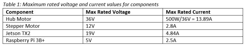

Note that voltage adds in series and capacity adds in parallel. Thus, the cells are connected in a 10S13P configuration, i.e.: 10 cells in series and 13 cells in parallel. As mentioned above, the battery was designed to accommodate any future component additions as the design evolved. However, for the components listed above, a 10S8P battery pack would have been adequate but perhaps it wouldn’t offer the best range per charge.
APPROXIMATE RANGE
In a perfect world (without COVID-19), the speed and range would have been determined empirically if the project had proceeded as planned. But here are some highly approximate calculations:


Comments