Battery Pack: Part 3 - Implementation
- Munifa

- Apr 7, 2020
- 2 min read
Updated: Apr 8, 2020
CAPACITY TESTING

After we received recycled laptop batteries from eCycle Solutions, we disassembled all batteries and sorted the cells. Most of the cells we collected were Samsung ICR18650-26C and Samsung ICR18650-26D, so these are the cells we decided to use. The remaining cells were returned to be recycled.
The capacity of each cell was tested twice using a lithium-ion cell capacity tester. Following the capacity tests, 130 cells with capacities in the 2500mAh to 2600mAh range were selected to be used in the battery pack.
WIRING
After the cell holders and lids were designed and 3D printed the battery was ready to be assembled based on the wiring diagram shown below. For more details regarding the 3D model designs, refer to the blog post titled "Battery Pack: Part 2 - 3D Model Design/Fabrication".

Nickel-plated lithium-ion cell contacts were
placed into each cell holder slot, using springs for negative terminals and tabs for positive terminals. The solder lug on each cell contact was pushed through the slit so it could be soldered at the back of the cell holder. The 12AWG wire segments (shown in blue in the wiring diagram above) were aligned through the loops to ensure that they stayed in place and didn't short together as the bike moved. One end of a 2cm segment of fuse wire (shown in purple in the wiring diagram) was soldered to the cell contact solder lug. And, the other end was soldered to the 12AWG wire segment (blue). Then the series connections (orange) were added and 11 sense wires (green) were connected as shown in the diagram. The 11-pin header on the other end of the sense wires connects to the BMS board. The overall negative of the battery pack also connects to the B- terminal of the BMS board.

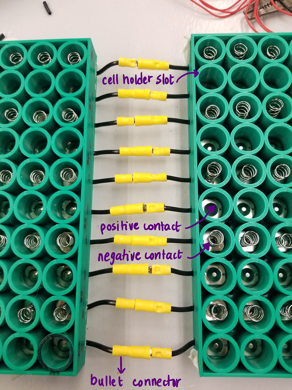
The overall battery pack is a 10 by 13 array of cells. However, due to the limitations of our 3D printer, the battery holders were split into two parts, a 10 by 7 array and a 10 by 6 array. Both parts were assembled as per the description above. Then the two parts were connected using crimped bullet connectors.
For charging the battery, a power barrel connector jack was added. The negative of the barrel connector was soldered to the C- terminal of the BMS, and the positive was connected to the overall positive of the battery.
ASSEMBLY

After placing the cell contacts in the cell holders and soldering all the connections, a lid was placed on top of the cell holders to cover the exposed wires. Then the cells were inserted into the cell holders. And finally, the top and bottom cell holders were compressed together and held in place using duct tape. We also added a battery capacity monitor later to keep an eye on the battery level.

MATERIALS REFERENCED


Comments